
Custom Hoof Rasps by Drawing and Tang Fit
Send a drawing when your finished rasp needs more detail than a catalogue handle can give you. Our flat double-sided model lists 45 and 50 mm body widths and chopped or milled tooth options. That gives you a useful starting vocabulary for a prototype with a specified work area, two face cuts and a proprietary handle fit.
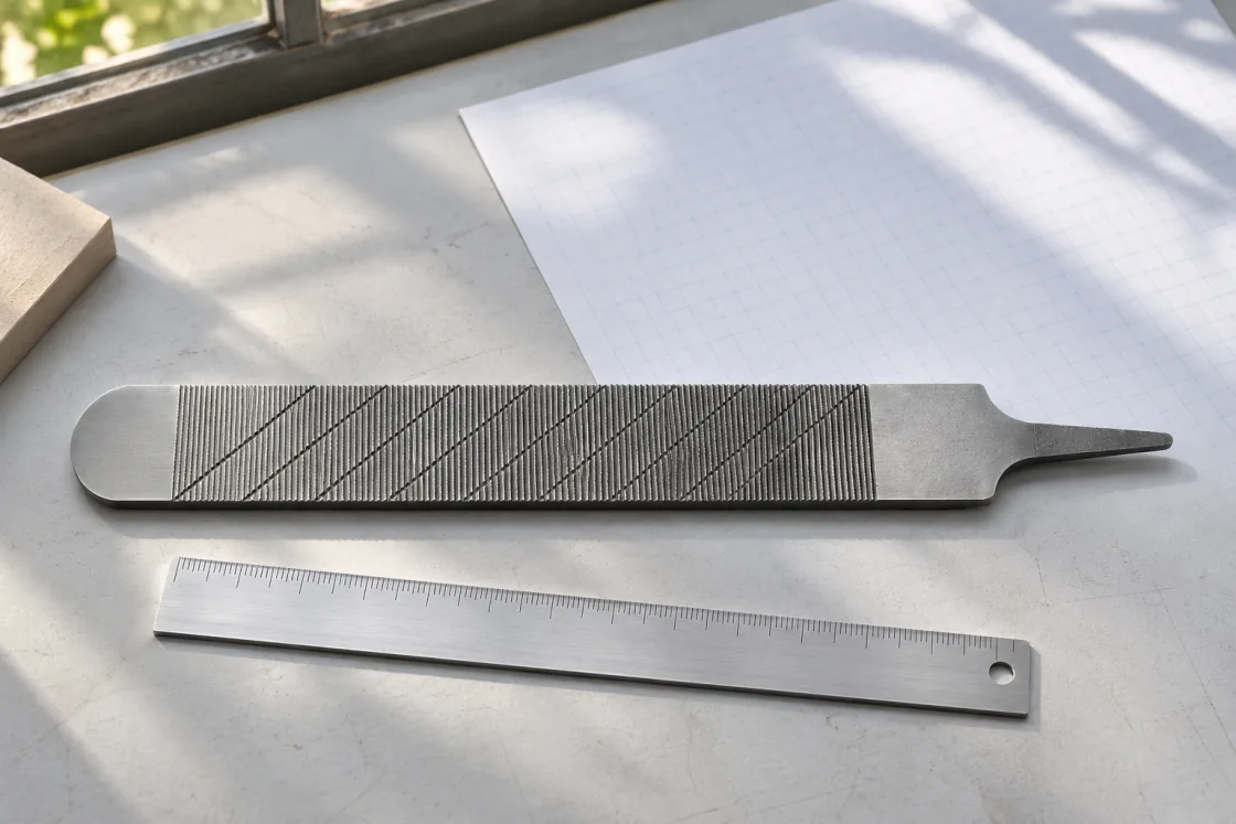
A Drawing Package for the Two Faces and Tang
A drawing should explain which features must match and which are open to a proposal. Attach a clear side view and separate face A and face B views.
| Drawing field | Catalogue illustration | What your drawing needs |
|---|---|---|
| Blade geometry | Flat body gives 350 mm at 14 in and 4.8 mm thickness | Length, width, thickness, nose outline and measured locations |
| Tooth zones | Chopped or milled options are named for the flat model | Face A and B, tooth direction, active limits and intended cut |
| Handle interface | Bare stainless rasp body has two working faces | Tang root and tip, taper, insertion depth and shoulder profile |
Working Width and Tooth Pattern
Our flat double-sided rasp lists 45 and 50 mm catalogue widths and chopped or milled tooth configurations. These entries show the kinds of fields to document. We can review the width, tooth zones and face pattern you request as separate specifications.
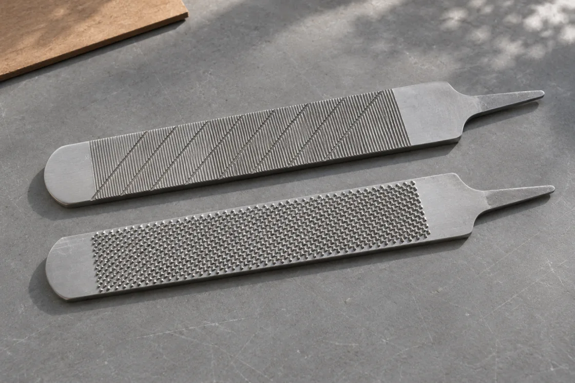
Prototype Measurements and Acceptance
Use one record for both the printed drawing and the physical sample. A tooth-layout change can affect a different area from a taper change. Mark the exact points, expected values and approved tolerances for each feature.
- Critical dimension
- Nominal value, tolerance and measuring point
- Face A and B
- Assigned cut and the boundaries of its working area
- Fit check
- Matching physical handle, intended seating and exposed shoulder
- Revision
- Drawing ID and prototype ID on the same record
The Handle Interface
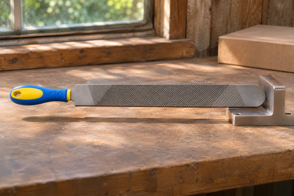
If you already use a proprietary handle, send its socket geometry and insertion depth. Our unhandled stainless hoof rasp is an example of a bare body, and a useful way to discuss the difference between a blade specification and a handle-fit test.
The Drawing-to-Sample Sequence
We can use the drawing to review the project scope and discuss a sample. Confirm the features the buyer will measure and the test sample quantity. Keep the signed-off revision with any later purchase order.
- Submit
- Drawing, purpose and volume
- Review
- Feasibility, material and inspection requirements
- Sample
- Prototype and fit evaluation
- Release
- Approved revision with the purchase order
A Separate Line for Tooling and Changes
Specify the material designation and any hardening evidence you need on the drawing. A grade, hardness and face pattern describe different things. Ask for the quoted configuration and supporting test information to match the same revision, especially when moving from a reference model to a new production version.
- Drawing version
- Name the agreed revision in the quote
- Tooling
- Record scope, ownership and charges as agreed
- Change request
- Decide who signs off the next sample
Using a Physical Sample Alongside the Drawing
A reference tool can clarify the finish and the way the grip meets the steel. Where the original is a discontinued product, follow our reference sample guide and mark which details should match and which can change.
Prototype Approval and the Next Order
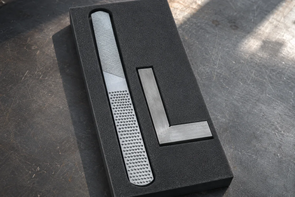
Record the prototype’s measured dimensions and keep a fitted-handle photo if the grip is part of the design. Keep production and reorder documents tied to that sample, as described in the batch quality guide.
- Prototype check
- Measure, fit and keep the accepted sample
- Volume order
- Use the approved revision and agreed checks
A Drawing Review with the Right Inputs
Send the most recent drawing, a few details about the intended job and your target quantity. Include handle drawings and test requirements when they affect the prototype.